Scenario 2: Single or multi-rack with LVRT requirement
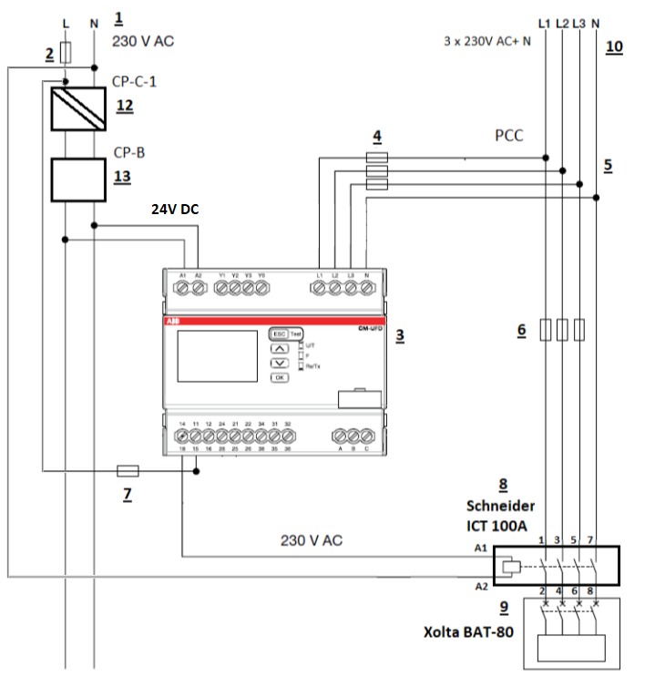
The figure below shows the wiring schematics for grid protection and coupling switch for a single or multiple battery racks and with LVRT requirement. You'll find a figure legend later in this section.
The following table is a legend for the figure above:
|
Number |
Description |
|---|---|
|
1 |
Single-phase 230V AC supply from the public grid – powers the ABB grid protection relay. |
|
2 |
Protection fuse (or MCB |
|
3 |
ABB CM-UFD.M31(M) grid protection relay. |
|
4 |
Voltage measuring circuit – protected by 3P, 10A protection fuses (or 3-phase MCB), connected to L1, L2, L3 inputs of the CM-UFD.M31(M). |
|
5 |
Point of common coupling (PCC |
|
6 |
Protection fuses for the connection between grid and XOLTABAT-80/BAT-80 AC. See the XOLTA BAT-80 and BAT-80 AC installation manuals for specifications: https://xolta.com/manuals/. |
|
7 |
Protection fuse (or MCB) 1P, 10A for each utilised relay (R1, R2, R3) of the CM-UFD.M31(M). |
|
8 |
Schneider Electric Acti 9 iCT 4-pole contactor – 100 A, 230 V AC coil, 4NO (used as coupling contactor). |
|
9 |
XOLTA BAT-80 is used in this example, but it can also be BAT-79 or BAT-80 AC. |
|
10 |
Public grid three-phase voltage: 3 × 230V AC + Neutral. |
|
12 |
ABB CP-C.1 24/5.0 power supply (1SVR360563R1001) – provides 24V DC. |
|
13 |
ABB CP-B 24/3.0 power supply (1SVR427060R0300) – provides 24V DC. |