Connection schematics – single-line diagrams and components
The following figures show single-line diagrams for a single and multi-rack installation of XOLTA battery systems.
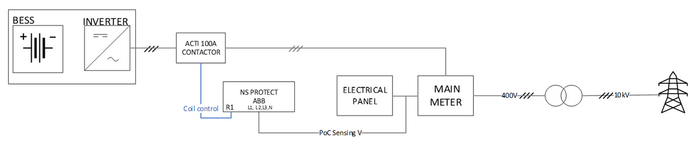
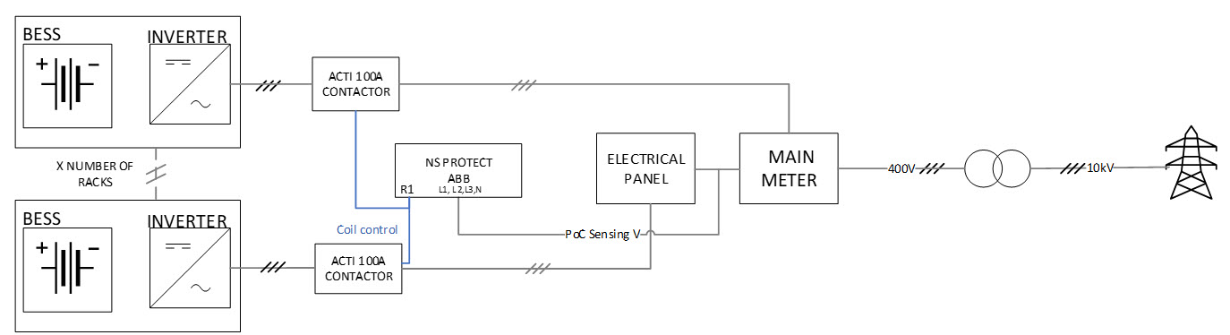
Each battery rack requires a single Schneider ACTI 100A contactor.
The ABB grid protection relay (CM-UFD.M31) includes three relay outputs (R1, R2, R3). Each output can control up to six Schneider iCT 100A contactors. This allows a single ABB relay to support installations with up to 18 racks.
Use the table below to determine the required components:
|
Example |
Required installation |
Required Schneider ICT 100A contactors |
Required number of ABB CM-UFD.M31 grid protection devices |
|---|---|---|---|
|
1 |
1 x BAT-80 |
1 |
1 (1x ICT 100A wired to R1) |
|
2 |
6 x BAT-80 |
6 |
1 (6x ICT 100A wired to R1) |
|
3 |
12 x BAT-80 |
12 |
1 (6x ICT 100A wired to R1) (6x ICT 100A wired to R2) |
|
4 |
18 x BAT-80 |
18 |
1 (6x ICT 100A wired to R1) (6x ICT 100A wired to R2) (6x ICT 100A wired to R3) |
|
5 |
24 x BAT-80 |
24 |
2 (6x ICT 100A wired to R1 of grid protection 1) (6x ICT 100A wired to R2 of grid protection 1) (6x ICT 100A wired to R3 of grid protection 1) (6x ICT 100A wired to R1 of grid protection 2) |
Next, connect the ABB CM-UFD.M31(M) relay according to the diagram below. For a complete overview of terminal functions, see the table below.
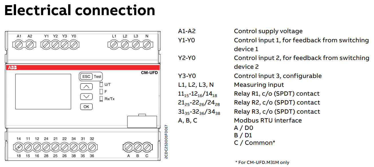
A detailed description of the connectors that are used with the XOLTA battery systems are shown in the table below:
|
Description |
|
|---|---|
|
A,B,C |
Modbus RTU (only in versions CM-UFD.M31M and CM-UFD.M33M) Note: Not to be connected. |
|
Y1, Y2, Y3, Y0 |
Feedback signals from switching devices corresponding to relays R1, R2, R3 Note: Not to be connected. |
|
A1, A2 |
Supply voltage (either 230V AC or 24V DC). Note:
|
|
L1, L2, L3, N |
Input for voltage monitoring at PCC |
|
1115-1216/1418 |
Electrical connections for Relay R1: 1115 - Common 1216 – NC Note: Not to be connected. 1418 – NO |
|
2125-2226/2428 |
Electrical connections for Relay R2: 2125 - Common 2226 – NC Note: Not to be connected. 2428 – NO |
|
3135-3236/3438 |
Electrical connections for Relay R3. You need to enable it in the settings. 3135 - Common 3236 – NC Note: Not to be connected. 3438 – NO |